Geomembranes for Landfills and ponds
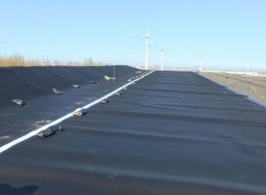
For almost 30 years, geomembranes, mostly high-density polyethylene (HDPE), have been employed as landfill bottom liners. They’ve also been utilized as tops for leachate ponds and, more recently, as floating coverings. They have behaved admirably in general, but there have been a few notable outliers that have helped us design even better systems.
Term definitions
Let us begin by clarifying the terminologies before going into depth about what is going on in this field:
- A containment facility’s barrier layer on the floor and sidewalls is called a liner.
- A solid waste containment facility’s barrier layer should be capped.
- A geomembrane floating on confined liquid that is sealed to the bottom liner along the pond’s borders and rises and falls with the liquid level is referred to as a floating cover.
As a result, a geomembrane liner contains valuable product and/or protects groundwater, a geomembrane cap contains landfill gas and prevents precipitation from turning into leachate, and a floating cover prevents odour emissions and evaporation/contamination of a valuable resource such as potable water.
HDPE’s Use Has Evolved
Because of its broad chemical resistance, high strength, relative inherent flexibility achieved without additives, weathering resistance that allows it to be left uncovered, and ability to be integrally fusion-welded by thermal methods rather than solvents and adhesives, HDPE essentially displaced PVC as the geomembrane of choice in the early 1980s. PVC seams could be ripped apart at the time, whereas HDPE seams could not.
It was quickly discovered that when HDPE contracted at low temperatures, the tensile strains created in the liner may generate brittle stress cracking (SC), a phenomenon previously seen and researched in HDPE natural gas distribution pipes. Tension cracking is brittle cracking that occurs under continuous stress that is less than the material’s tensile yield or break stress. SC was shown to be a function of resin composition, and so can vary significantly amongst HDPEs from various geomembrane producers. However, over time, formulations have improved to the point that SC is now uncommon in materials from well-known multinational HDPE resin and geomembrane producers.
Because of this vulnerability to SC, it is a normal design goal for geomembranes to serve just as a barrier and not as a load-bearing part of the lining system, necessitating the need for a fully supported geomembrane liner. While this is simple to execute on paper, it is extremely difficult to achieve in practise due to HDPE’s high coefficient of thermal expansion.
In practise, wrinkles appear that are quite tough to remove. As a result, when HDPE geomembranes are coated, they are inevitably pressured. As a result, two lining systems were created, with the secondary (lower) liner serving as a safety backup. This worked great as long as the leachate detection system (LDS) between the two geomembranes didn’t fill up with leaking liquid. The lining system would not leak if the hydraulic head on the secondary liner was avoided.
Both primary and secondary geomembranes contain a comparable number of inevitable faults, but the double system does not leak into the subgrade if the liquid seeping through the main (upper) liner is not allowed to build over the few flaws in the secondary liner.
Detecting leaks
The leak flow rates through the main liner were determined by collecting the leaking liquid. At the same time, in the late 1980s, electrical techniques for locating leaks in geomembranes covered by liquids and soils were established. Approximately 25% of leaks occur during the installation of the geomembrane, with the remaining 75% occurring once the geomembrane is covered. With increasing liner area and decreasing relative amount of detail work in the installation, the number of leaks per unit area reduces. Above 2 ha, the leak frequency declines from around 12/ha to about 2/ha.
The electrical inspections revealed that the majority of liner installations leaked to varying degrees, owing to the efficacy of the construction quality assurance (CQA) process. Geomembranes were mixed with compacted clay liners, and later geosynthetic clay liners (GCLs), to create composite liners in an attempt to reduce leakage. The theory behind GCLs, which are generally two layers of geotextiles needle-punched together with bentonite granules between them, is that a breach in the geomembrane will hydrate the bentonite, allowing it to inflate into and close the leak.
The ‘intimate’ contact between GCL and geomembrane prevents lateral liquid transmission over this interface, lowering individual main liner leakage substantially. Wrinkles in the geomembrane, on the other hand, remain a possible issue, resulting in locations where the geomembrane is not in touch with the GCL and areas where the liner is strained and more likely to collapse.
Bulldozers are also frequently used to scrape the tops off wrinkles while spreading cover dirt. As a result, twin composite lining systems have been developed.
While this is ideal in principle, in reality wrinkled secondary liners are covered with wrinkled HDPE geonet/geotextile composite LDSs, which are then covered by wrinkled primary geomembranes. Stresses are not avoided; intimate contact is not obtained; and creases in the secondary liner result in water ponding on the secondary. Nonetheless, the majority of lining systems appear to be functioning properly.
Is it possible to achieve zero leakage?
‘Satisfactorily’ does not imply that the main liner is completely leak-free. Electrical surveys have demonstrated that expecting zero leakage is an unrealistic goal. Primary liners that do not leak do exist, but they cannot be guaranteed. Many double lining systems with merely drips coming out of the LDS have been installed, but the owners have been dissatisfied.
Demands for the liner to be repaired have simply resulted in higher leakage flow rates. In the United States, a maximum permissible leakage rate through a main geomembrane with 300 mm of hydrostatic head (the regulatory maximum) is normally 200 litres/ha per day, over which leaks must be located and corrected. It is 5000 litres per hectare per day in municipal wastewater treatment plants with a 2 metre head. This is far too high; a more reasonable figure would be around 2000 litres per hectare per day.
The significance of proper drainage
This is especially true in wastewater treatment plants, where bacterial activity in spilled water might continue and further reactions with subgrade vegetative debris produce enormous amounts of methane and other gases. There is no route for these gases to escape to the gas vents at the tops of the slopes since there is standing water beneath the liner. The gases build up, and the liner rises until it breaches through the water’s surface, transforming into a ‘whale.’
The water level beneath the liner is the same as the water level above the liner, and whales generally contain gas above the water level. Under the liner, there must be a good drainage system that can remove the water and that has the capacity to vent any created gases upgradient to the slope vents. A standard non-woven geotextile cushion is insufficient.
Capping landfills
Geomembranes have also been used to cover landfills, both to prevent precipitation penetration and to trap and remove landfill gas, in order to reduce the quantity of primary leachate that must be treated and disposed of (LFG). While HDPE has been used in caps, the preferable material is frequently linear low density polyethylene (LLDPE) or another more flexible polymer, such as PVC or flexible polypropylene (fPP), which may better withstand the strains and resulting stresses associated with differential waste settlements.
As a result, the geomembrane must be able to adjust to the differential settlement profile without causing stresses that might lead to stress cracking. In their as-manufactured state, less crystalline materials like LLDPE and fPP are not vulnerable to SC.
What advantages may exposed geomembrane caps provide?
Exposed caps alleviate difficulties with soil coverings, reduce cap cost and building time, and improve air space. Wind uplift, LFG pressure uplift, UV radiation and higher temperatures, as well as high volumes and rates of precipitation run-off, must all be factored into the design. In the United States, eight exposed geomembrane caps (EGCs) were built utilising reinforced fPP, HDPE, and an ethylene interpolymer alloy (EIA). In Florida, one of the HDPE EGCs managed to endure two storms.
Over the past ten years, the fPP-R cap has functioned admirably, and it is going to be extended for another ten years. Because of its low coefficient of thermal expansion and lack of wrinkles, PP works effectively. Wrinkles in HDPE tend to travel down slopes but do not migrate back up slopes when temperatures drop.
FAQs
Can geomembranes be used for gas barrier applications?
Yes, geomembranes can be employed as gas barriers to prevent the migration of gases such as methane or radon through the soil or substrate.
What is the typical thickness of a landfill liner geomembrane?
The thickness of landfill liner geomembranes is usually in the range of 1.0 mm (40 mil) to 2.5 mm (100 mil), depending on regulatory requirements and site-specific conditions.
How do geomembranes perform in high-stress applications?
Geomembranes designed for high-stress applications have enhanced strength and puncture resistance. These properties enable them to withstand the stresses associated with heavy loads or traffic.
source on Google
 Case Study: Crawfish Hatchery Building Project in Bhutan
 Case Study: Purulia Mega Projects – Raw Water Reservoir
 Reservoir Project Success: Harnessing the Power of HDPE Liner and Geotextiles by Ocean Non Wovens