How do you install geogrid on a retaining wall?
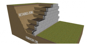
The installation of a Geogrid Retaining Wall is described in detail below. These instructions are intended to serve as a guide and instruction manual for effectively and efficiently installing a MagnumStone project. The user is free to utilise any and all of the information supplied.
MagnumStone is available in three different batter temperatures: 0 degrees, 2.4 degrees, and 4.5 degrees (setback) For availability, contact your local producer.
Face textures differ from one creator to the next. For additional information on the styles available, please contact your local sales representative
It is usually suggested that the owner of the geogrid retaining wall project contact a skilled engineering consultant for all projects.
Before you dig, give us a call. Most governments and jurisdictions provide these services for free. They will come to the site and mark the locations of any underground facilities.
Table of Contents
The Geogrid Retaining Wall is being planned.
Use spray paint or pegs to mark the bottom and top of the geogrid retaining wall excavation.
Before beginning excavation, establish correct elevation points for both the bottom and top of the wall.
Backfill Zones should not be filled with organic materials.
During construction, store and safeguard excellent quality backfill materials from the elements.
Excavating The Geogrid Retaining Wall is a retaining wall made of geogrid.
6 to 8′′ (15 to 20cm) below the first course, excavate and prepare a Sub Base Leveling Trench. This will be filled with a solid 3/4-inch road base.
Figure 1 – Cut away about 6′′ (15cm) from the rear and front of the total depth of the base course for the Leveling Pad Trench. MagnumStone Standard Unit, for example, is 24′′ + 6′′ (front) + 6′′ (back) = 36′′ total (61 cm + 15 cm + 15 cm = 91 cm).
The typical burial depth or embedment depth for retaining walls is 6′′ to 12′′ (15 to 30cm), or 10% of the overall height of the wall. To achieve the right embedment depth, follow the engineers’ cross section information or design specifications.
Excavate the cut line to a slope of at least 2 to 1.
Fabrics for Sub-Base and Base Stabilization
Compact Sub Base with a Standard Proctor Density of 95% or higher
Before compacting, remove any organic or inferior soils from the Sub Base and replace the with adequate reinforced fill materials (Optional) place 5′ to 6′ wide Foundation Stabilization Fabric on top of levelling pad trench Base Stabilization Fabrics assist prevent sub base materials from mixing with the gravel base levelling pad during compaction. Fabric also gives the base levelling pad more structural bearing stability.
Gravel Leveling Pad (Compact)
The foundation levelling pad is typically 3/4′′ (20mm) road smash gravel or comparable.
Compact Gravel Leveling Pad with a Standard Proctor Density of 95 percent or higher
Moisture Balance The gravel’s content will aid in achieving optimum compaction.
The base must be level from front to rear and side to side. As the wall gets taller, any flaws will be magnified.
The First Course of MagnumStone Retaining Wall Blocks is Being Installed
To construct the back of the first course of units, place a steel stake at either end of the levelling pad.
Attach a tight string line to the stakes on either end to use as a guide for aligning the backs of each MagnumStoneTM base block.
Due to strong gusts, the distance between the steel stakes on the string line may change.
SecureLugs are not used in the manufacturing of MagnumStoneTM base blocks that are put on the levelling pad.
Place each unit on top of the levelling pad so that the level gravel is not disturbed.
The Gravity Retaining Wall should be backfilled.
Backfill the MagnumStone blocks with a material that has been authorised. Over backfill materials with the right moisture content, use a plate vibratory compactor (for smaller lifts) or a roller / vibrating compactor.
Backfill in lifts or layers appropriate for the soil conditions and compaction machine size.
The success of the completed product is dependent on proper compaction.
Geogrid Retaining Wall Drain Pipe
The slope of a fabric-wrapped or perforated drain pipe should be sufficient to drain water in the proper direction towards each Drain Pipe Outlet.
Every 30 or 50 feet, a drain pipe outlet may be found.
To assist prevent particles from migrating into the pipe, Sock Wrapped Perforated Drain Pipe can be installed in the Horizontal Cores.
Drain Gravel Installation Clear Crush Drain Gravel is installed in the vertical and horizontal hollow cores after the backfill materials have been laid and compacted.
To allow for SecureLug connection, the Clear Crush Drain Gravel should be 2′′ below the top of the units.
It is not necessary to compress Clear Crush Drain Gravel.
Before putting the second course of MagnumStoneTM Blocks, sweep the top of the MagnumStoneTM Blocks clear of all rock and debris.
Ensure that the backfill materials behind the wall are flush with the tops of the units.
As far as possible, ensure that the backfill materials are compressed and level.
Cut Geogrid Reinforcement to the length indicated in the design when installing geogrids to retaining walls. Cross sections of each project are displayed, along with geogrid lengths.
Geogrids are made in two different ways. Is it bi-axial or uni-axial? The strength of a Uni-axial grid is only in one direction, which must be perpendicular to the face of the wall during installation. The bi-axial grid can be installed in two directions: perpendicular to the face of the wall and lengthwise (verify that the lengthwise direction is consistent with the Engineer’s design).
The geogrid’s orientation, strength, and length are critical to the project’s success.
Each Geogrid length should be put parallel and next to one another, but never overlapping.
Geogrid and Second Layer Connection
Place the Geogrid as far forward as possible on the MagnumStoneTM units without exposing it to the face.
Place the following course of MagnumStoneTM units on top of the lower units, half-bonding the bottom units with Geogrid.
The two SecureLugs will lock the Geogrid into the gravel core by fitting firmly into the hollow cores of the two units below.
To accommodate the SecureLugs connection, the gravel in the bottom units will be recessed 2′′ or more.
Complete the unit installation on the Geogrid. Courses that are reinforced
Assemble each unit against the one next to it, making sure there are no gaps between the unit joints.
Maintain the tension of the Geogrid during backfilling with stakes or backfill materials.
Driving machinery directly on top of Geogrid is not recommended.
Geogrid Layers with Backfill Reinforcement
Place materials from the back of the wall towards the end of the Geogrid to backfill the Reinforced Zone.
After laying and compacting backfill materials, place drainage gravel in the cores.
Install and compress backfill materials in no more than 8-inch lifts. For maximum lift information, see the compaction equipment.
Geogrid Retaining Wall Installation Final Grading
Ensure that the retaining wall’s top and bottom receive final grading.
During strong rains or surface runoff, make sure to protect newly planted soil from erosion.
source on Google
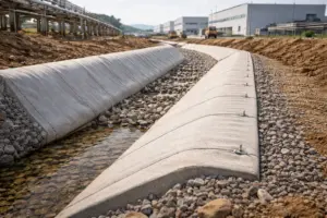 Case Study: Application of GCCM in Industrial Infrastructure
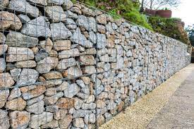 What are Gabion Walls? – Application, Advantages & Disadvantages
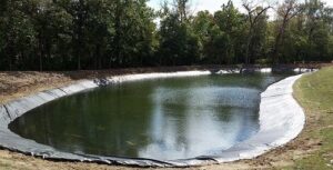 Geosynthetics for Storage of Water in Agriculture