Use of geogrid in the construction of railroads
A geogrid is a polymeric (i.e., geosynthetic) material made up of linked parallel sets of tensile ribs with large enough openings to enable soil, stone, or other geotechnical material to pass through. Reinforcement and separation are their major tasks. The mechanism(s) through which the engineering qualities of the composite soil/aggregate are mechanically enhanced are referred to as reinforcement. Separation refers to the physical separation of incompatible materials so that they do not mix, such as ballast and sub-ballast or sub-ballast and subgrade. Geogrids were initially manufactured by Netlon Ltd. in the United Kingdom. Tensar Corporation (now Tensar International [18]) launched geogrids in the United States in 1982.
Dr. Brian Mercer (1927–1998) invented the Netlon® technique in the 1950s, which involves extruding polymers into a net-like structure in one step. In 1959, he established Netlon Ltd. in the United Kingdom to produce the product. Some polymer straps and strips were formed into grid-like products during the 1970s as a result of Dr. Mercer’s additional innovative research and development work on extruded net technology, but the first integral geogrids were developed in the late 1970s and first used in various applications in the early 1980s. Several UK institutions, including Leeds, Nottingham, Oxford, Sheffield, and Strathclyde, were extensively involved in a comprehensive programme of research that studied polymer technology in the early phases of geogrid development.
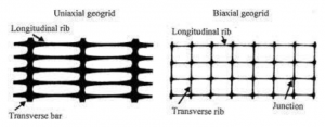
Netlon Ltd. created two types of extruded geogrids in the beginning: biaxial and uniaxial. They were created by punching and drawing a thick sheet of polyethylene or polypropylene to produce apertures and improve the technical qualities of the ribs and nodes that resulted. Original uniaxial extruded geogrids were made by stretching a punched sheet of high-density polyethylene in one direction under strict circumstances. The long-chain molecules of the polymer were oriented in the direction of draw throughout this process, resulting in a product with high one-directional tensile strength and modulus. The punched sheet of polypropylene was stretched in two orthogonal directions to create biaxial geogrids. As a consequence of this procedure, a product with high tensile strength and modulus in two perpendicular directions was created. The grid apertures that resulted were either square or rectangular.
At this time, many types of geogrids are commercially accessible in various nations. Commercially available geogrids include woven and welded geogrids in addition to extruded geogrids. Woven geogrids are made by weaving polymeric fibres (typically polyester or polypropylene) into a mesh design and then coating it with a polymeric lacquer. Welded geogrids are made by fusing polymeric strip joints together. When compared to other forms of geogrids, extruded geogrids have performed well in pavement reinforcement applications. Commercial uniaxial and biaxial geogrids for soil reinforcement currently available have nominal rib thicknesses of 0.5–1.5 mm and joints of 2.5–5 mm. The perforations of soil reinforcement grids are typically rectangular or elliptical in form.
Geogrids have been utilised widely for the building of earth-supported and earth-retaining structures such as mechanically stabilised earth (MSE) retaining walls, steep slopes, and other structures over the last 25 years. Reinforced soil foundations are a less well-known but growingly common application of this technology (RSF). The layered composite of granular fill and layers of polymeric reinforcements acts as a beam in this application, minimising unit stresses in the foundation soil beneath shallow spread footings. Geogrids have also been utilised as a single layer within or at the bottom of base or subbase granular fill in the construction of motorways and airfields. In these sectors, design and construction protocols are well established [8, 20, 21]. As a result, most of this information has been used to paved and unpaved structures that handle rubber-tired traffic like trucks and planes.
Mechanism of reinforcement
In general, geogrids are utilised to strengthen track bed materials in one of two ways. The key benefit of including it at the bottom or inside a ballast layer is that it extends the maintenance cycle, or the time between ballast cleaning and replacement procedures. The second application of geogrids beneath a rail line is to strengthen the sub-ballast . The major goal of the geogrids in this situation is to raise the effective bearing capacity of a soft subgrade.
The reinforcing processes related with the interaction of geogrids with unbound aggregate have been researched by a number of writers. For example, Perkins [14] proposed that there are four distinct reinforcing processes. These reinforcement processes are detailed in the following paragraphs:
- Because the aggregate is contained by the geogrid, the amount of lateral spreading is reduced.
- Confinement increases the lateral stress inside the aggregate, resulting in increased stiffness. Each load cycle’s dynamic (recoverable) deformation is reduced as a result.
- A higher aggregate modulus leads in a better vertical stress distribution on the underlying subgrade. As a result, the surface deformation will become less and less homogeneous.
- Lower vertical strain due to a decrease in shear stress inside the subgrade.
There are currently just a few studies in the literature that give a quantitative study of the reduced effective vertical stress (′v) that occurs when geogrid reinforcement is included in unbound aggregate. In order to build the Incheon International Airport in Korea, Shin et al. [17] conducted stress testing on ground reclaimed from the sea. A plate load test (circular plate; diameter B = 0.3 m) was done on a granular mattress as part of the field test setup. Testing was done both with and without geogrid reinforcement. A pressure cell was used to measure the stress transmitted (′max) by the load on the plate below its centre at a depth d (=0.45 m). Stress distribution, with the stress boundary, v′, inclined at an angle to the vertical.
- In comparison to the unreinforced case, the magnitude of rises for a particular configuration of geogrid reinforcement and q. The magnitude of ′av decreases as the value of decreases.
- is a function of q for a particular reinforcement system.
Gabr et al. [7] came to a similar result based on large-scale model studies in the laboratory.
Ballast with geogrid reinforcement performs well.
Ontario, Canada’s Queens University
The findings of a large-scale model test programme with a single tie/ballast system erected over an artificial subgrade with varying compressibility were reported by Bathurst and Raymond [3]. (also see [4]). The tie was put over a 450 mm thick ballast layer with a width of 250 mm and a depth of 150 mm. For ballast reinforcement, a biaxial geogrid was employed. The reinforcement depth below the tie (D r) varied between 50 and 200 mm. The rail tie was subjected to cyclic loads (peak load of 85 kN per rail tie) with frequencies ranging from 0.5 to 3 Hz. This resulted in a bearing pressure of 370 kN/m2, which corresponds to the magnitude of dynamic stress felt by ballasts directly beneath the tie for track moduli ranging from 14 to 84 MN/m/m of rail [15].
A maximum number of load repetitions, equivalent to 2–20 million total axle tonnes in track, were applied to the tests. Relationship between permanent deformation and cumulative axle tonnes for stiff subgrade support (CBR = ), flexible subgrade support (CBR = 39), and extremely flexible subgrade support (CBR = 1), respectively. The presence of geogrid in the ballast layer minimises permanent deformation for any given cumulative axle tonnage, as seen in these data. However, when the CBR of the subgrade decreases, the impact becomes more significant. D r = 100 mm.
The geogrid’s position in respect to the tie’s bottom determines how much stress is transferred. The correlations between cumulative tonnage, permanent deformation, and reinforcement depth D r are based on the data provide. According to the plots the best value of D r appears to be between 50 and 100 mm. However, practical issues, like as construction and upkeep, may make this depth unacceptable. As a result, a value of D r 200 mm is likely to be more acceptable.
Derby, United Kingdom, British Rail Study
British Rail Research conducted three large-scale laboratory studies utilising a rolling load rig to assess the benefits of adopting geogrid reinforcement in ballast sections [10]. Extruded biaxial geogrid reinforcement was used in the ballast layer for two of these experiments. A third test was conducted without reinforcement and served as a comparative portion. A simulated soft subgrade was placed under the ballast in all three tests, and the results were compared to a similar unreinforced test conducted on the test facility’s solid floor; this test was conducted to see how the test sections conducted on a soft subgrade compared to a section constructed on a competent formation. The test setup is depicted schematically.
The terms initial lift and residual lift are used in the UK to define the performance of a restored ballast section following further trafficking. The following were the four tests carried out in the British Rail Research study:
- Control section—soft subgrade with no reinforcement,
- reinforced section—soft subgrade with geogrid 50 mm above the ballast-subgrade interface (D r = 250 mm),
- reinforced section—soft subgrade with geogrid 100 mm above the ballast-subgrade interface (D r = 200 mm), and
- control section—solid subgrade with geogrid 100 mm above the ballast-subgrade interface (D r = 200 mm),
source on Google
 Flood Control with Geobags: A Sustainable and Effective Approach
Geogrids, Geosynthetics, Insights
Geosynthetics in Construction of Roads Subgrade Stabilization with Geogrids Turnkey Sports Project – Dehradun Case Study